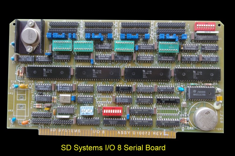
SD SYSTEMS I/O8 Serial IO Board
This was a very late (1983) - and now
relatively rare SD System board. It was a serial I/O board ideally
suited for a multiuser system with serial ports. It ran at high speed and
had outstanding configurability.

The I/O-8 was an Zilog 8530/8531 serial communications controller based
interface board which fully complied with the IEEE-696 specification for the
S-100 bus. The I/0-8 board was designed to provide serial communication
capability from an S-100 computer to various Data Communications Equipment
(DCE) or Data Terminal Equipment (DTE). RS-232 signal levels were handled by
MC1488 and MC1489's.
The following is a list of technical references applicable to the I/0-8:
IEEE-696 Bus Specification
8530 SCC Product Specification (Zilog)
8531 ASCC Product Specification (Zilog)
58167A RTC Product Specification (National)
EIA-RS-232C Specification
Board Features Include:-
1. Serial Ports
4 ports asynchronous DTE/DCE
4 ports synchronous/asynchronous DTE/DCE
8 I/O ports are addressable to any 8 port boundary in 64K
2. Baud Rate
Each channel software selectable, full duplex 50 to 19,200 in
asynchronous mode using x16 internal clock
Up to 1Mbit/sec in synchronous mode using external clock
Up to 307,200 in synchronous mode using xl on board internal
clock (2.4576 MHZ)
3. Data Bits
5,6,7, or 8 data bits/character
Stop bits -I, 1.5, 2
Clock rate -xl, xl6, x32, x64
Parity -odd, even, or none
Error detection -parity, overrun, CRC or framing
Data encoding -NRZ, NRZI, FMI, FMO
4. Interrupts
Receiver ready
All receive characters
Special receive condition (parity error, framing error,
overrun error, and end of frame in SDLC)
5. Real Time Clock (RTC) With Battery Backup
6. Software Programmable Interrupt Rates
7. Standby Interrupt While Powered Down
8. Millisecond Through Month Counters
9. User Readable Switch
The real time clock (a 58167A) had software programmable interrupt rates,
battery backup and 56 bits of RAM and various
clock counters. A software example was given for a CP/M 3 time clock. The
backup RAM was used with the onboard battery to store the time on power
down. The clock could keep accurate time in this way for up to 6
months.
One nice thing about the board was it only used 8 I/O ports which could be
any 8 byte boundary in the 64K I/O space of the S-100 bus. Any one
8530 is addressed via an onboard control port. Once selected, 4 ports
control and get data from that selected 8530. The RTC address
select register used one port along with a port to read the data. The
readable switch also used a port. SD Systems in all their examples use ports
A0H - A7H.
The manual for this very useful board can be obtained
here.
Other SD Systems S-100 Boards
8024 VDB
ExpandoRAM
ExpandoROM
SBC
VersaFloppy I & II
Z8800
PROM-100
I/O8 Serial Board
4KRAM
Other Boards
This page was last modified
on 01/08/2011


